I gathered the info and posted this on the P1WOC which may help:
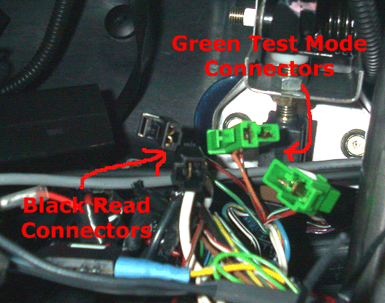
If your CEL is constantly illuminated (CEL – Check Engine Light), you can do a do a CEL check to obtain the fault code. To do this, you need to locate the 2 green ‘test mode’ connectors under the steering column.
Alternatively if there is no CEL illuminated, fault codes can still be logged on the ECU. These can be read using the black 'read memory' connectors.
 If your CEL is constantly illuminated:
 find the green connectors and connect them, then turn the ignition on (do not start the car). You should now here lots of clicking and fans spinning from the engine bay. Take a look at the CEL and you should notice that the CEL will flash in a sequence. This flashing sequence translates a fault code.
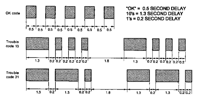
If you get a steady flash every 0.5 seconds there is no fault code present.
If there is no CEL illuminated: find the black connectors and connect them, then turn the ignition on (do not start the car). You will not hear any clicking or fans spinning from the engine bay. Take a look at the CEL, if it remains on or if you get a steady flash every 0.5 seconds there is no fault code present. If it is flashing, this flashing sequence translates a fault code.
Once the fault code has been rectified, the ECU should be reset simply by disconnecting the battery for 30min, then starting the car and letting it idle untill the fans come on.
This is how you work it out...

A long flash equals 10, and a short flash equals 1. Total them up to get your error code. You should also be aware that if more than 1 error code is present, the CEL pulse sequence will change. The change in sequence is easy to identify.
You are also able to read previous fault codes that the ECU has stored. This is helpful if you you’re CEL flashed up and is not constantly illuminated and if you just want to be inquisitive.
To do this, you need to locate the 2 black ‘read memory’ connectors (pictured above) under the steering column. Join the connectors together and switch the ignition on, then use the ‘pulse’ method as above to obtain the fault codes the ECU has stored.
As with the CEL pulse in test mode, more than 1 error code may be present, causing the CEL pulse sequence to change. The change in sequence is easy to identify.
These are the Subaru trouble codes:
Subaru Code Subaru Trouble Code Description
1 Engine Speed Signal Circuit
11 Crankshaft Position Sensor
12 Starter Signal
13 Camshaft Position Sensor
21 Engine Coolant Temperature Sensor
22 Knock Sensor
23 Mass Air Flow Sensor Circuit
24 Idle Control System Malfunction
24 ISC Valve (Stick)
24 Open/Short in ISC Valve Circuit
26 Intake Air Temperature Sensor
27 ATF Temperature Sensor Circuit
28 Knock Sensor #2
29 Crankshaft Position Sensor 2
31 Throttle Position Sensor Circuit
32 A/F Sensor #1 System
32 A/F Sensor #2 System
32 Oxygen Sensor
33 Vehicle Speed Sensor
35 CPC System
36 Turbine Speed Signal
37 Rear O2 Sensor Circuit / A/F Sensor Circuit Malfunction
38 Torque Control Signal #1
38 Torque Control Signal #2
38 Torque Control Signal System
38 Torque Permission Signal
39 Traction Control System
42 Idle Switch
43 Accelerator Pedal Switch
44 Turbocharging Pressure Control Signal
45 Pressure Sensor
48 Lean Burn System
49 CO Resistor
51 Neutral Position Switch
53 Antenna
53 Anti-Quick Operation Mode
53 Communication Error (Time Over)
53 EGI Control Module EEPROM
53 IMM Circuit Failure (Except Antenna Circuit)
53 IMM Control Module EEPROM
53 Key Communication Failure
53 Reference Code Incompatibility
53 Use of Unregistered Key
54 Air Intake System
55 EGR Valve Lift Sensor
56 EGR System
61 Air Suction Control Solenoid Valve
62 Exhaust Manifold Valve Negative Pressure Control Solenoid
64 Relief Valve Control Solenoid Valve 1
64 Relief Valve Control Solenoid Valve 2
65 Differential Pressure Sensor
66 Twin Turbocharger System(H)
66 Twin Turbocharger System(S)
66 Twin Turbocharger System(T)
66 Two Stage Twin Turbocharger System
67 Exhaust Manifold Valve Positive Pressure Control Solenoid
68 Turbocharging Pressure Control Output Signal #2
71 Shift Solenoid Valve
72 Shift Solenoid #2 Circuit
73 Low Clutch Timing Solenoid Circuit
74 Brake Clutch Timing Solenoid Circuit Malfunction
75 Line Pressure Duty Solenoid Circuit
76 Brake Clutch Pressure Duty Solenoid Circuit Malfunction
77 Lock-Up Duty Solenoid Circuit
78 Tiptronic Solenoid System
79 Transfer Clutch Duty Solenoid Circuit
81 Torque Up Control Valve
85 Charger System Circuit Malfunction
86 CAN (Communication System)
87 Variable Induction Solenoid Valve Circuit Malfunction
88 Fuel Pump Circuit Malfunction
89 VVT Systems (L)
89 VVT Systems ®
91 TCS Relief Valve
92 Electrical Generation Control Signal Circuit Malfunction
93 Vehicle Speed Sensor #1 Circuit
94 Lateral G Sensor Signal Circuit Malfunction