Time for a proper update! Its been several months since Ive last saw the build so, with a Saturday spare and the commencement of the 2012 British Rallycross Championship looming, I took a little drive to check the car out. Having seen the latest situation with the build Im happy to report lots of good news but, sadly, a bit of bad news too.
Starting with the good stuff, the build has
really moved on since the last time I was there. Although at first glance it still seems just a shell, many of the items that were previously sitting on the shelf awaiting a location in the new car have now been positioned and all the provisions for attachment made. Prior to my arrival pretty much everything was out of the car, so Kevin (rather kindly) placed the major items back in to give an idea of the configuration for the finished product. Hence if you look carefully in the pictures youll see some things arent sitting square and look rather vaguely fitted in place: thats not sloppy workmanship, just where the parts are resting for the photos!
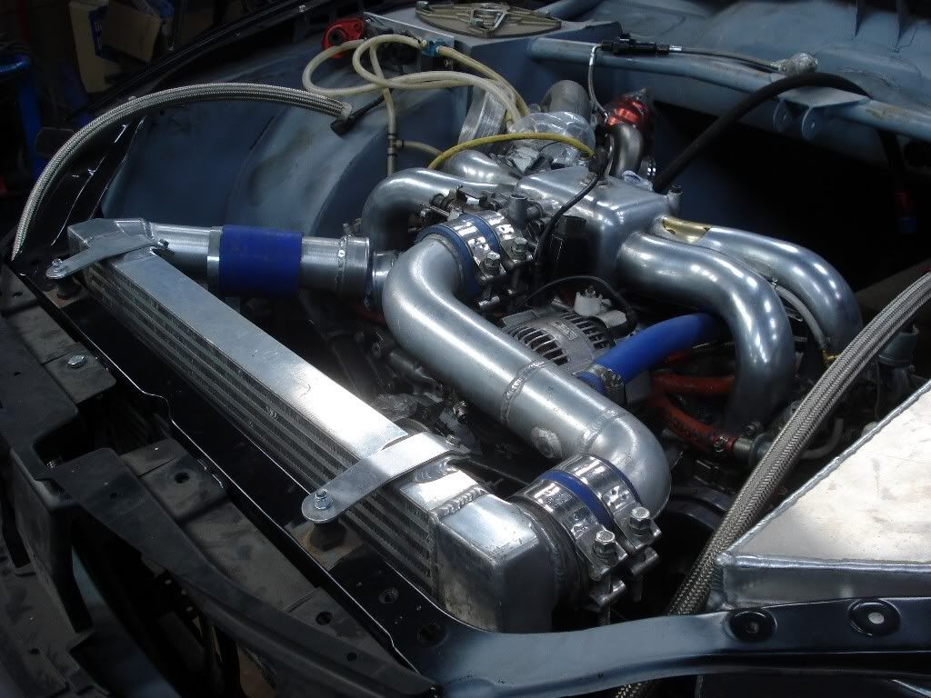
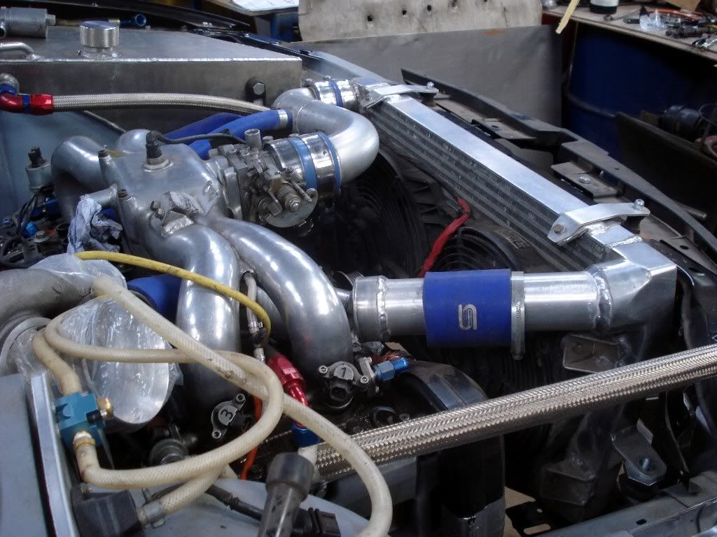
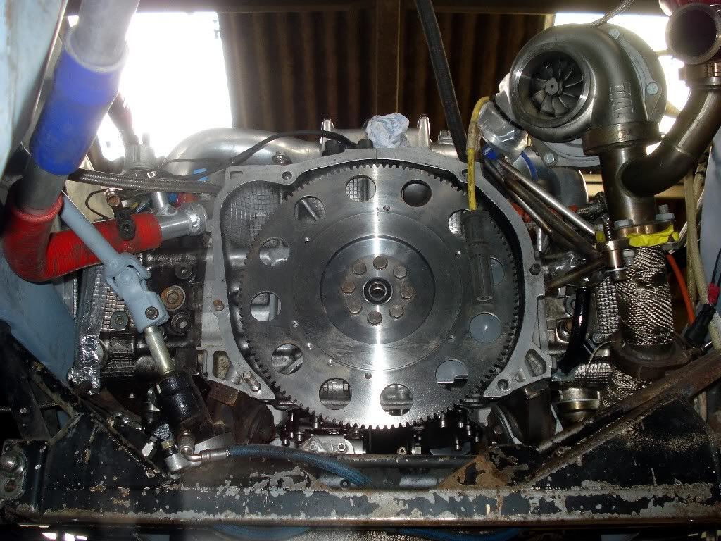
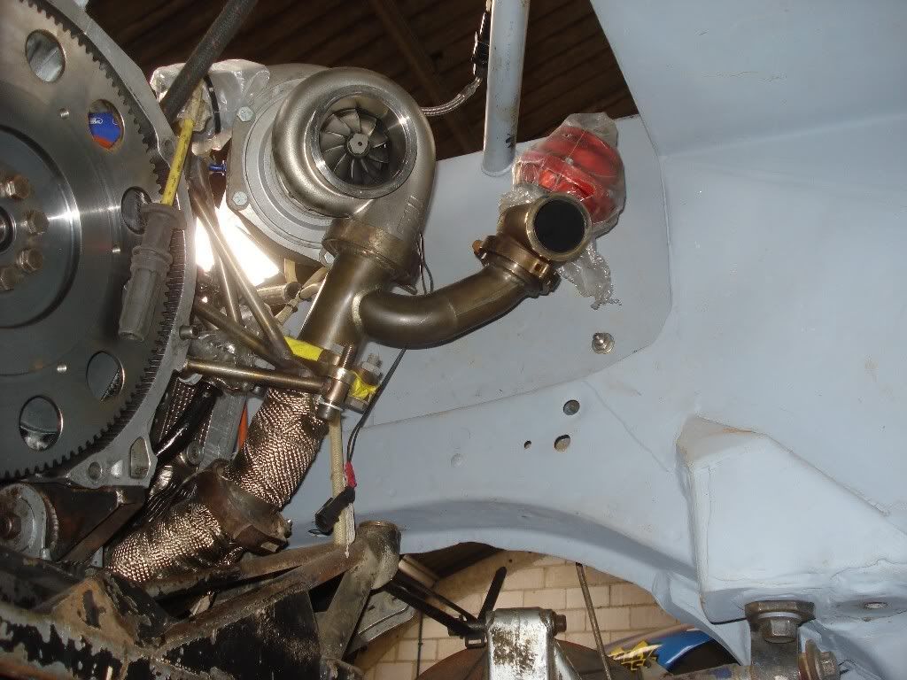
Beginning at the front and with probably the most significant of all components is the newly built engine, sitting in situ and ready to go. Nothing too radical with regards to the layout when compared to a conventional road car:

The gearbox is currently on the bench, awaiting its final tweaks:
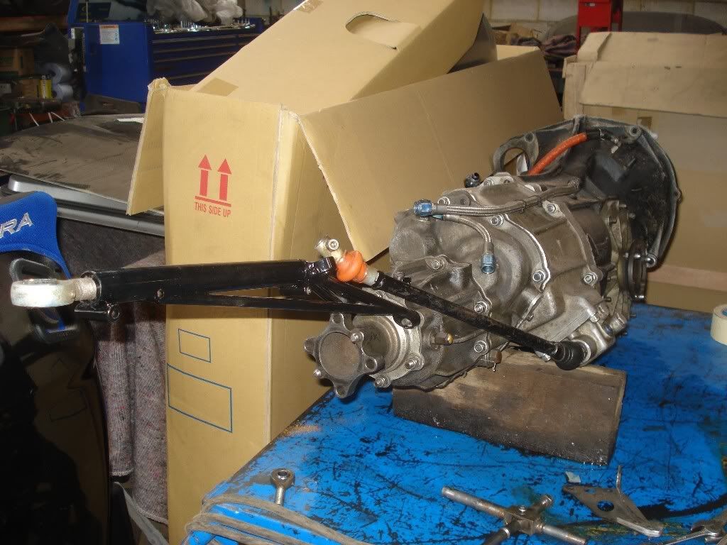
Given the differing location of the driver and the gearbox between the old GC8 and the new GR, the shift lever needed considerable extension. Gartrac took up the challenge and have manufactured a very smart looking extension lever. Due to shifting the driving position to the left of the car, some final tweaks are still needed to this, hence why not all the mechanism is not currently in place.
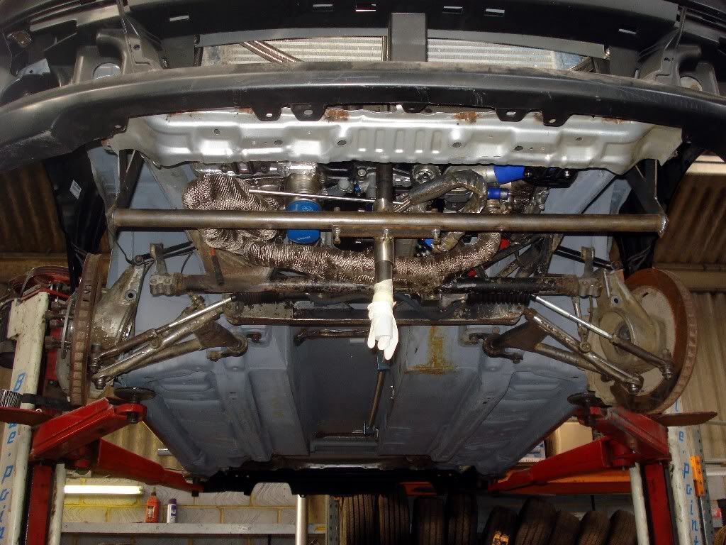
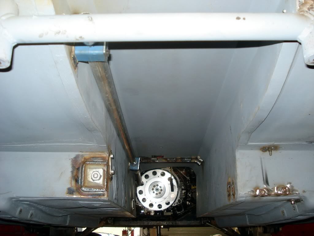
The underside of the car at present, clearly showing the complete S5 front end fully transplanted onto the new car:
Self explanatory really, but some mighty APs now fitted:
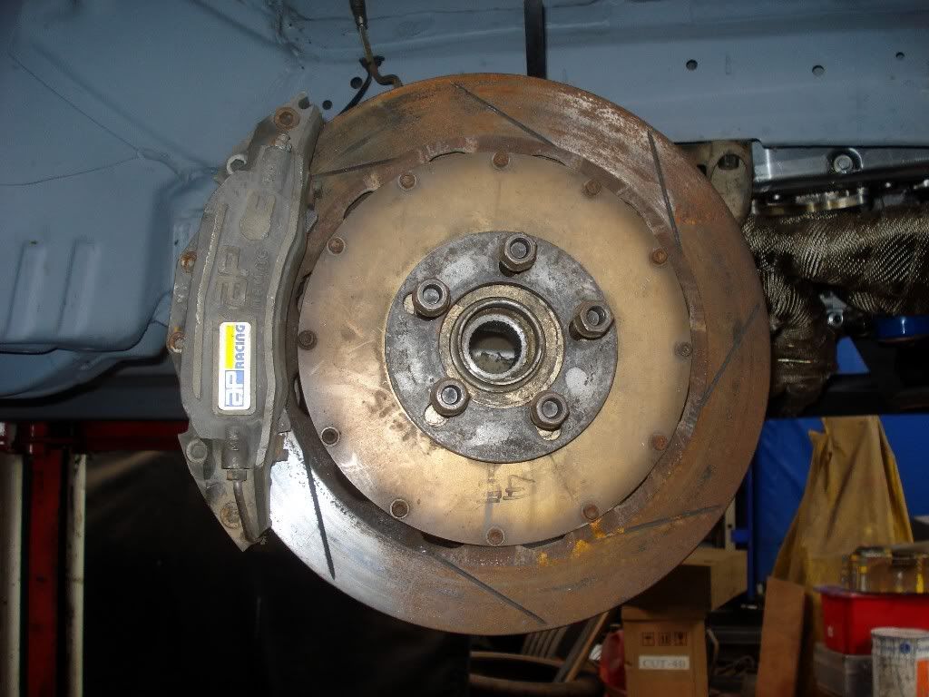
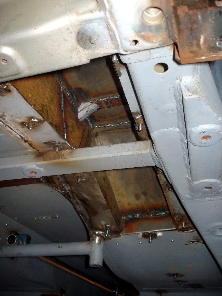
Underside view of the right side wishbone and chassis mount:
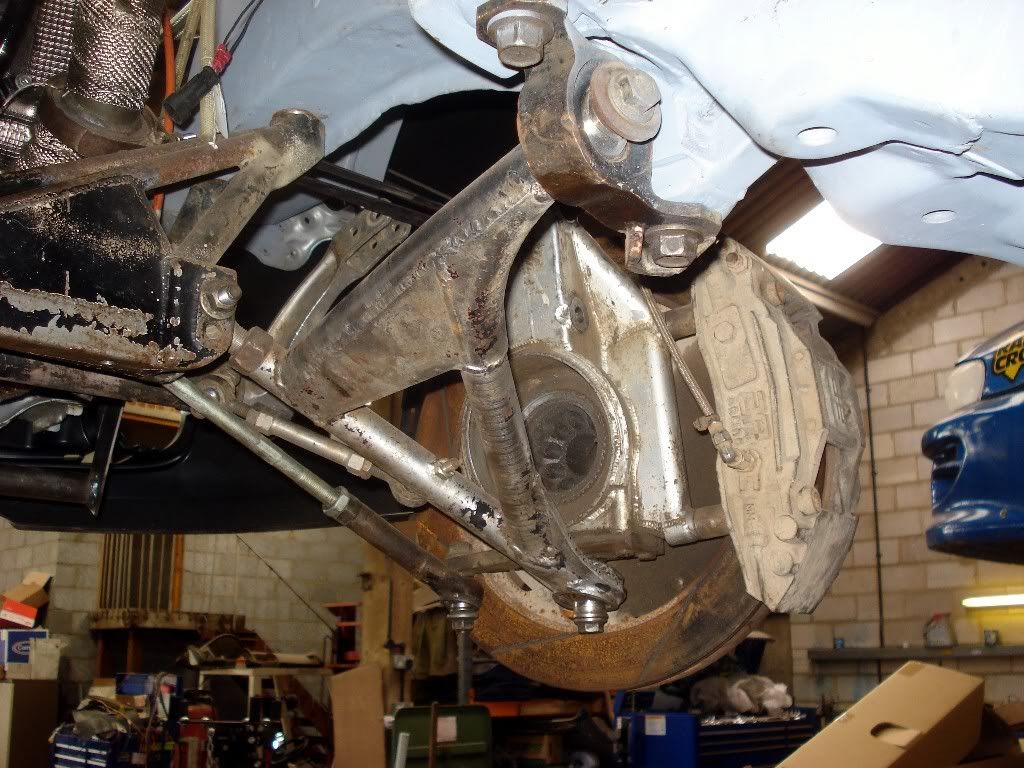
As with a lot of items on the car the finish on these parts is rough at present. Throughout the build components are constantly being modified though so, logically, its only when everything is in place and finalized that the whole lot will be taken off and painted. Conveniently there are actually two ovens within a stones throw of the garage so, when the time comes, its a case of wheeling the car next door for painting.
Just in case you are wondering what the protrusion below the engine is, it isnt a Scalectrix inspired modification, but is part of an additional engine mount fabricated for working on the car with the gearbox out: basically with the gearbox removed the whole engine wants to rotate forward on its mountings, so this frame supports the weight across the front side allowing work to continue under the car without fear of the engine making a bid for freedom.
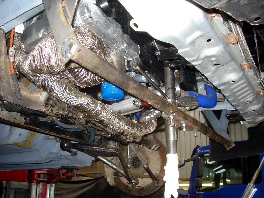
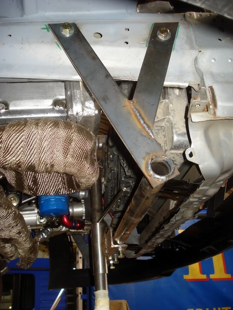
The vertical protrusion on the frame is scheduled to be chopped off once the frame is no longer needed and can be removed from the car, but of course this cant happen until the gearbox is ready to go back in: hence an emergency stop gap modification of white tape to its lowest point after someone walked into it!

The engine brace is one of loads of little things that have been done to make the car as modular as possible, thus individual areas of the car can be easily worked on without having to take half of it to bits. This extends from major component to little details, such as using bolts where you might normally use rivets, purely for the ease of quickly removing and refitting parts to and from the car.
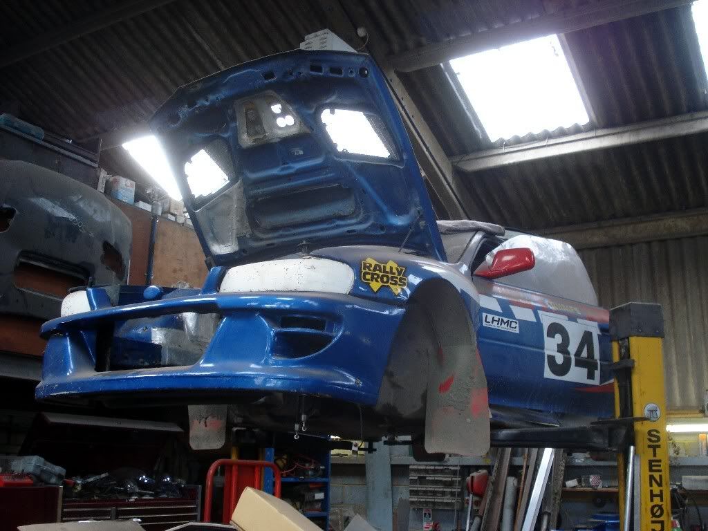
The GC8, robbed of its innards, sitting on the ramp awaiting a new home:
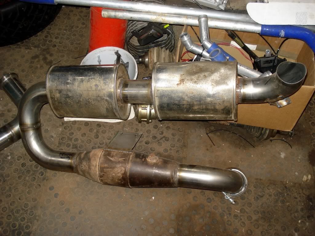
The exhaust system, which was originally planned to be 4 in diameter, has been dropped to 3. This system has been largely fabricated from scratch and is now ready for fitment, though its not in place at the moment due to the ongoing work on the underside and engine bay. You can trace the exhausts path though, starting from the back of the turbo and dropping into the transmission tunnel
then along the right side of transmission tunnel
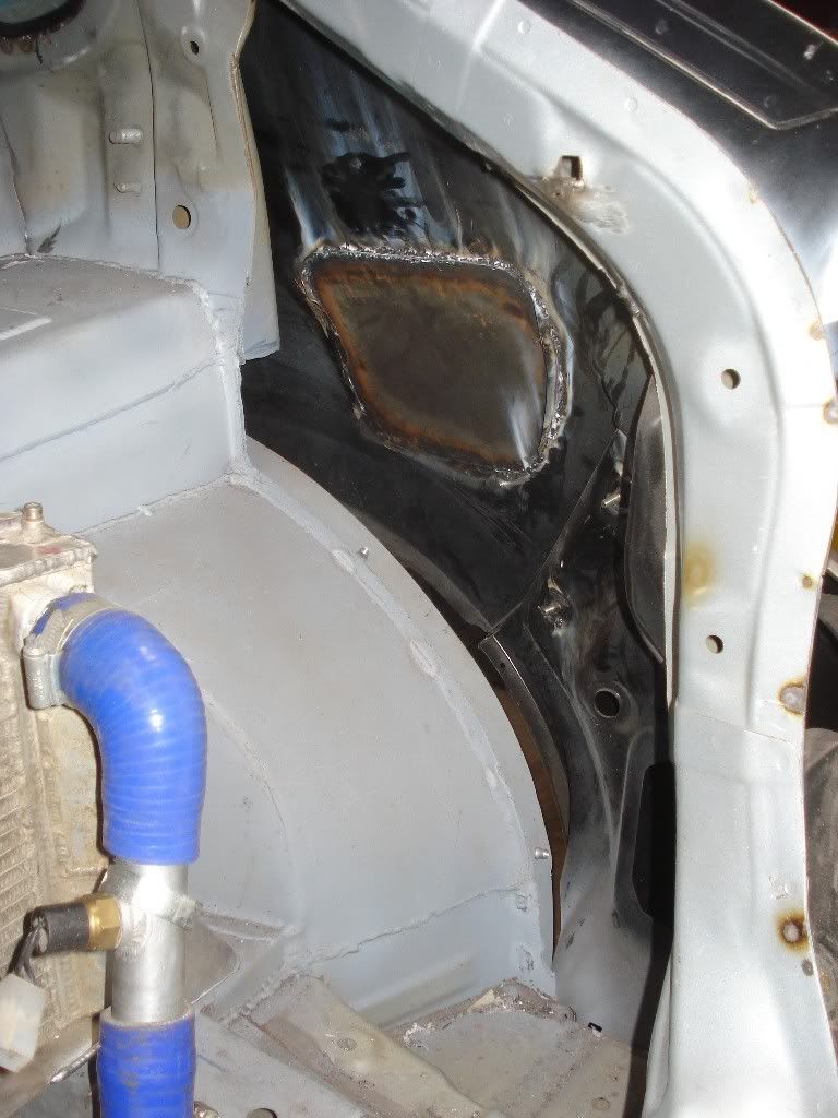
turning upwards and running into a void fabricated in the rear floor of the car, thus allowing the exhaust to run over the back axle
before dropping back down and ending with a silencer which will runs across the width of the car and exits on the right side of the rear bumper.
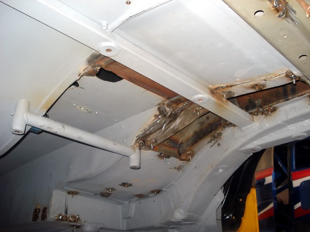
If you look carefully at the shot showing the length of the transmission tunnel, you can
just make out several attachment points on either side of the tunnel. These are for braces running across the width of the car which, other than providing the obvious benefit of additional underfloor bracing, have hoops mounted on them which go around the prop shaft.
The idea being that if the prop shaft does let go, the hoops will act as a containment ring of sorts and prevent the flailing shaft from causing any further damage. Its a very minor element in the design, but one of many influenced by hard lessons from the past and geared towards keeping the car as reliable as possible: and ensuring that any failure that does occur has the minimum knock on effect on the rest of the car.
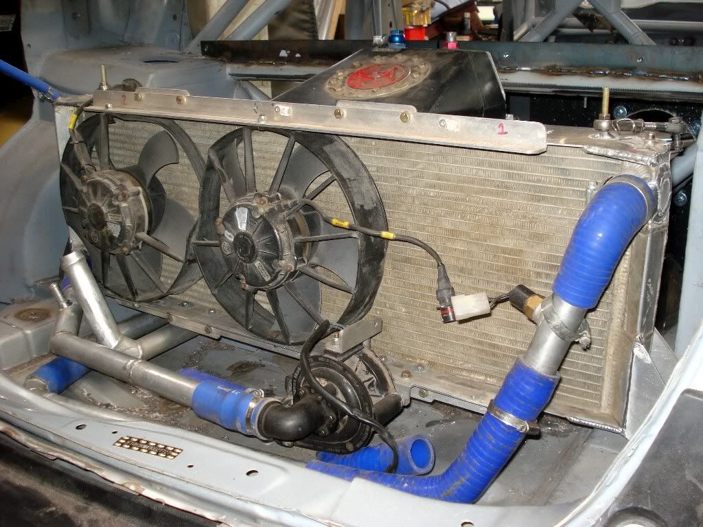
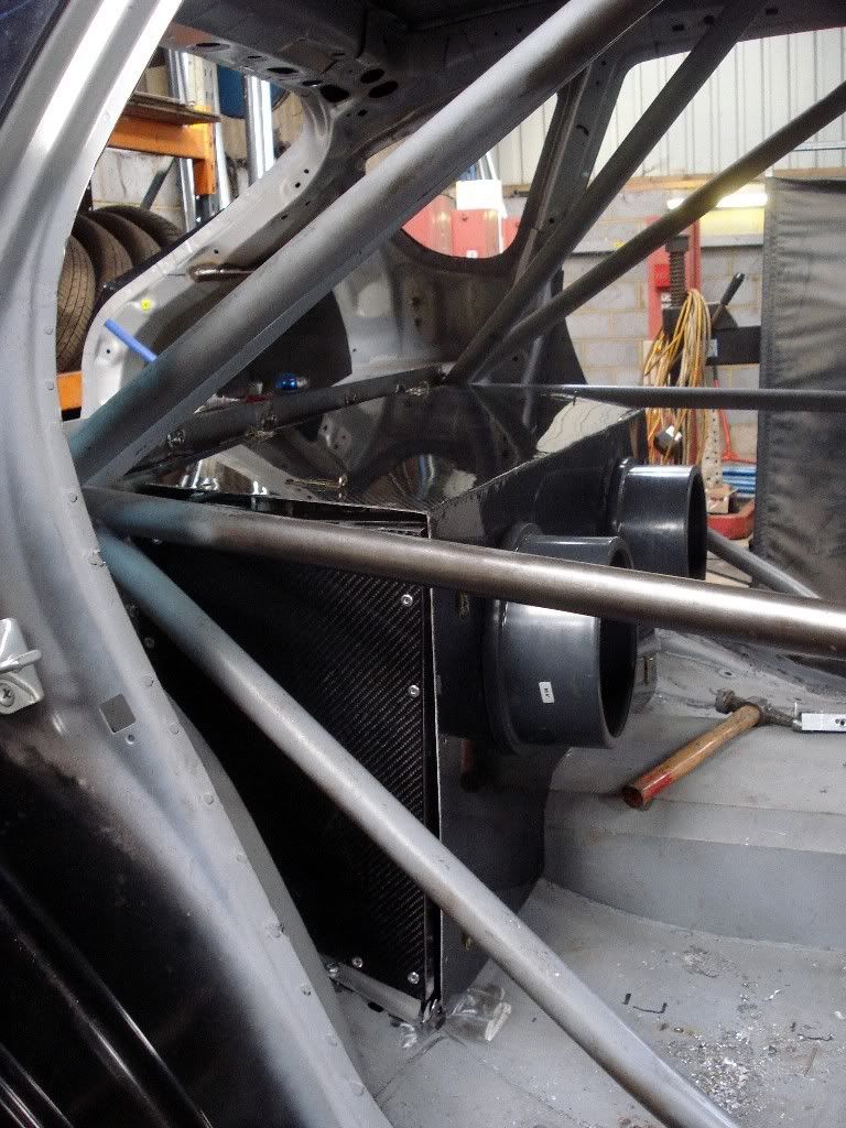
Moving back on top and its in the boot where the most visual progress has occurred. Last time I was there the layout of the radiator, fuel cell and associated ducting was just an idea in Kevins mind. Now everything has a firm location and attachment points have been prepared across the rear floor area. Looking from the boot inwards you have the radiator sitting right at the back of the car:
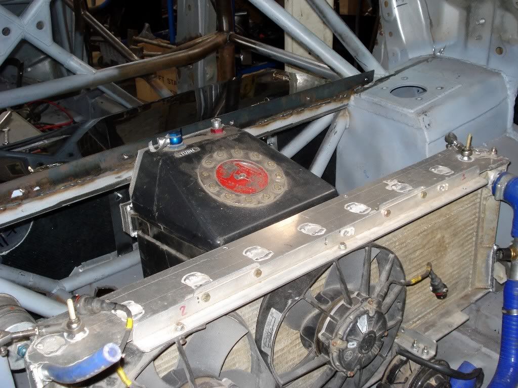
Immediately in front of that is the fuel cell:
Looking from the front of the car you can see the frame work for the radiator ducting:
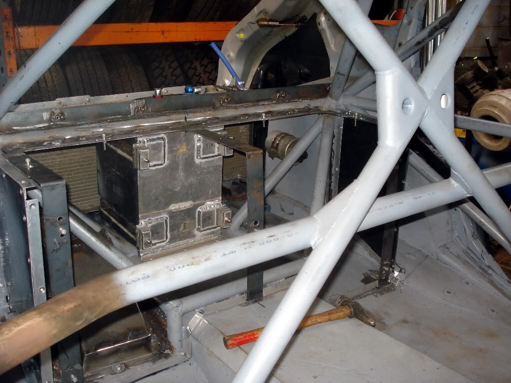
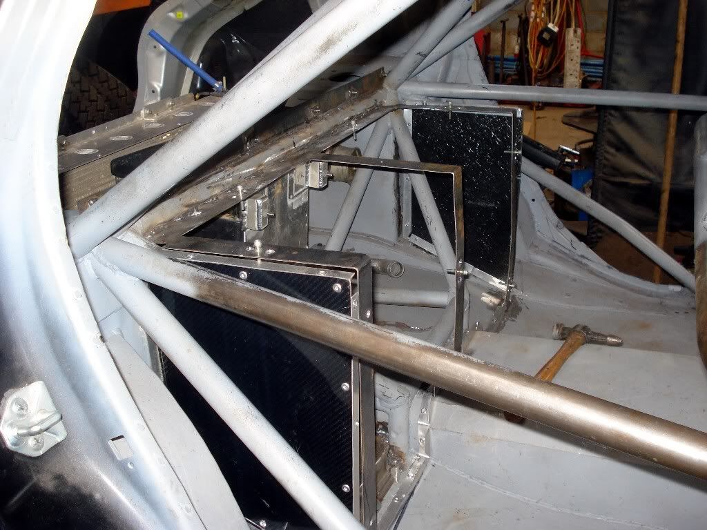
With the main box structure for the ducting intakes done in carbon fiber:
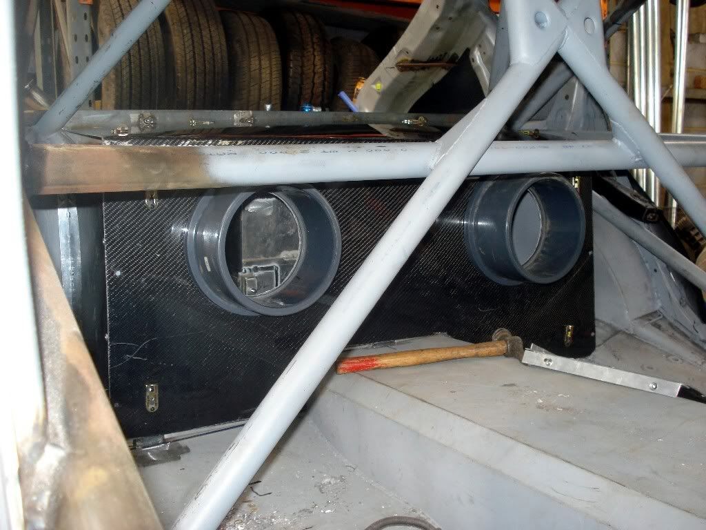
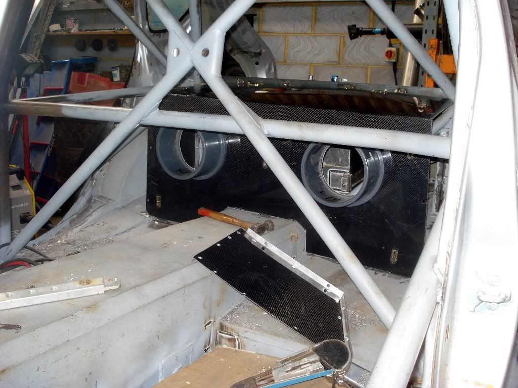
As mentioned above these items were dropped in situ purely for photography purposes, so obviously the air box wont have finger sized gaps at the joints when its properly fitted! With these bits sitting in place though, you can start to make sense of the internal design of the rear, where cool air will be drawn in though vents in the rear doors, pass through the radiator and exit via venting in the tailgate. I was shown the intakes for the cooling ducting which will be independently supported and sleeved, so the rear doors can still be opened and closed to allow quick accessibility to the back of the without having to dismantle the cooling system ducting.
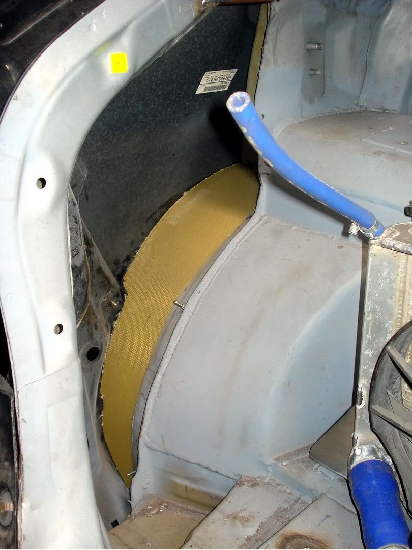
You can also see inside the rear wings when looking in the boot, where very little now remains of the original structure. The second photo below also shows a little glimpse of the top side of the arch liner which is currently being manufactured from scratch: